Measuring Valve Clearance
Introduction
This project originally started out to change the valve lifters, as there was a lot of noise coming from the valve train. This usually means a lifter is defective. The valve lifters in most cam driven push rod engines are hydraulic. Oil from the oil pump pressurizes the lifters, making them somewhat self-adjustable. Engines prior to the late 1950's had mechanical lifters and ajustable rocker arms that had to be adjusted from time to time to keep the engine running properly. This was part of the "tune-up" procedure that modern cars do not require. However, I discovered something very peculiar after disassembling the top of my engine that required me to measure the valve clearance to make sure is was in specification.
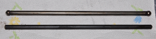
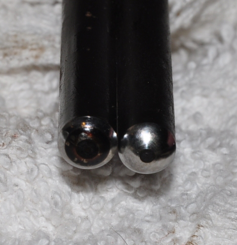
I found two different push rod types in the engine. Fifteen of the lower type and one of the upper type. The upper type is the three piece ball end type. These are what are typically found for replacement at the auto parts store. The photo on right shows the single piece push rods that are probably the original type. I purchased 16 of the ball end type to replace the all of the old ones.
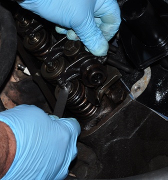
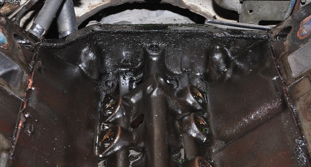
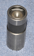
Show below is the lifter gallery. The lifters are the round objects running down the center of the crankcase. The cam, driven by the crankshaft, pushes on the lifters, which in turn push the push rods up. The rocker arm then transfers this motion to press the valve down at the correct time in the combustion cycle. In the middle is a new lifter. The view on the right shows the new push rods installed. All sixteen lifters and push rods were replaced.
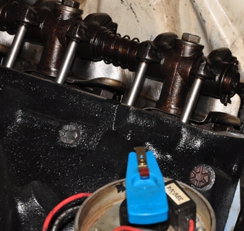
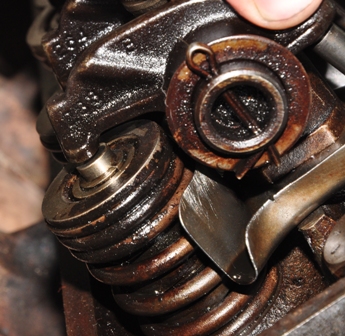
Since the lifters were new and hadn't been pumped up with oil, it was a good time to check the valve clearance. If it is out of specification, then different length push rods are available to correct any gap that is out of tolerance. This view shows the gap between rocker arm and the valve stem. The standard length push rod for the Ford 390 V-8 is 9.621". Push rods are available in 0.030" and 0.060" over and undersize.